In which no Raspberry Pi’s are seen.
TL;DR: It should be fairly straight forward to add a Raspberry Pi controlled heating and hot water system to a standard UK domestic set up and, more importantly, remove it again without messing with the existing set up. As a minimum you’ll need a Raspberry Pi and 4 relays. A few other bits and bobs wouldn’t go a miss though. The theory checks out, I’ve ordered the bits, come back next time to see what it looks like.
It occurs to me that for a long time we’ve had a thermostat in our homes which switches the heating off when it gets warm enough, but wouldn’t it be just as useful to have something which turns the heating on when it gets too cold?
This thought, together with a Raspberry Pi that wasn’t doing much and a strong desire to make my home more connected, led me to think about how I might control my heating system from, say, a smart phone. I’m far from being the first person to think of this idea, and there are loads of really good examples out there, but none of them did quite what I wanted in the way I wanted to do it. So I’m going to start from first principals and walk through this project design to try and build a removable & non-destructive add-on to an existing system. I’m writing this at the very start of the project, so I’ve no idea if it will work, if I will break some expensive components on way to getting it working, or if I will just give up before I get to the end. Let’s see.
Typical domestic hot water and heating systems
This may be UK specific. Here is a very very crude diagram of a typical home set up:
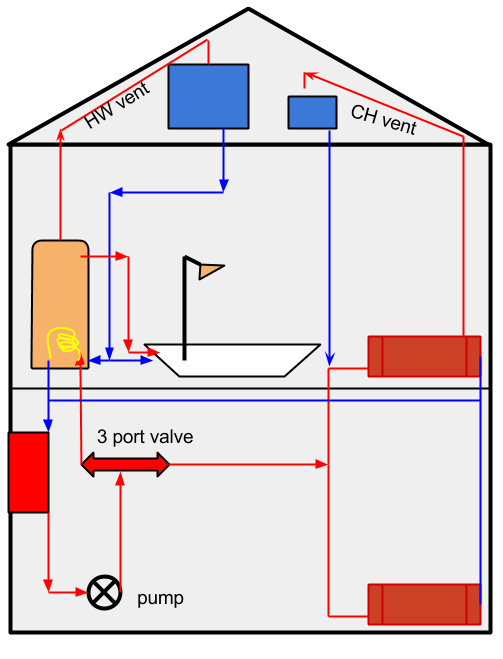
A crude diagram of how the central heating system works in a typical UK home.
The boiler burns gas and heats water. That hot water is circulated around the system (called the primary circuit) by a pump and can do three jobs. It can circulate through a heating element in a hot water cylinder and heat more water which is stored in the cylinder. Note that the water which circulates through the element does not come in to contact with the actual water it is heating, the two are kept separate for water quality reasons. The second job it can do is circulate through radiators in the home and hear the air. The third job is to do both. The hot water from the boiler moves around the primary circuit losing it’s heat to either the hot water in the cylinder or the air and eventually passes through the boiler again, heats up, and goes round and round again.
There are two “header” tanks of cold water in the loft. One is for the cold water to the bathroom for flushing the loo, filling the bath, brushing your teeth, that kind of thing. This tank also fills the hot water cylinder. The other is the header tank for the primary system and ensures that it can’t boil dry. Both use gravity and water pressure to make sure the water flows to where it is needed.
The system in the diagram is an “open” system. If the hot water in the cylinder gets too hot it can expand up the vent pipe and dump itself in to the cold water tank. The cold water tank can over flow to outside. If the hot water in the primary gets too hot it can expand up in to the header tank ready to be reused to fill the primary when the water cools.
There is such a thing as a sealed pressurised system which doesn’t have these vents. These are more complex and if you have one please be very careful in tinkering with the control mechanisms. In an open system, if you get things wrong and the boiler runs and runs you would end up with a lot of steam in the loft. In a pressurised system things can go pop and blast you with boiling water. That said, in an open system you could still end up dumping a header tank full of boiling water down on to the bedrooms below. People have died from this happening, so tinkering with the heating system is not something to be taken lightly.
In summary then; we have three things we can ask a system for:
- Make hot water
- Heat the house
- Make hot water and heat the house
And we have a number of key elements:
- Boiler
- Hot water cylinder
- Primary header tank
- Cold water tank
Typical electrical system to control hot water and heating
Once we understand how the wet bits fit together we can take a look at the electrical components:
Y Plan electrical wiring plan for central heating and hot water.
There are multiple “standards” for wiring up a heating system. You can find heaps of information on the excellent DIY FAQ wiki.
My system has been wired in the “Y Plan” configuration and if you have a single 3-port valve in your airing cupboard and a couple of tanks in your loft – then there is a good chance you have too. I will run through the wiring, and some of the inherent safety systems built in (which is why I’m keen to make sure my controller is a simple replacement for the existing controller, and is not a complete re-wire). Before we start though, a further word of caution. Mains electricity is lethal. You need be comfortable playing with this stuff to consider attempting anything to do with the heating system. It’s also probably illegal in UK due to some draconian restrictions on what a home owner can and can not do to the wiring in their own home. Don’t try this at home kids. A competent tradesman might be able to help you hook it all together.
The incoming mains supply goes through a double pole switch which will disconnect live and neutral when switched off. In this diagram, the live feed provides power to only the controller (sometimes you might see a parallel (switched and fused) connection to the boiler from that live). So first and foremost, all power to the components comes through the controller. Neutral is common to pump, boiler and valve and so is earth.
Thermostats are placed in series for both the hot water circuits and the heating circuits. These will physically break the circuit when a specific temperature is reached.
Let’s consider this example: I tell the controller to heat the water. It connects the live feed to the “HW ON” cable via point 6 on the diagram. The current flows to the cylinder stat, which allows the current through since the temperature is lower than the trigger point it is set to. The pump and the boiler are connected in parallel so you can’t run the boiler with out the pump running too (at least that’s the plan), and they are provided power via the room stat to point 8 on the diagram. The boiler is told to turn on, and the pump moves that heated water around the system. The hot water reaches the three port valve. The valve has an electrical actuator on which moves to set position depending on what electrical connections are made to it. In our case, no INPUT power is being applied to the valve, so it sits in it’s default position – which just happens to be “Hot water mode”, and so the heated water from the boiler passes through the hot water cylinder only. When the hot water cylinder get’s to the right temperature the thermostats clicks over to the other contactor and now no power is applied to the pump and boiler via the HW ON output on the controller. Instead, the grey wire, point 7 on the connector, is energised. This tells the valve that HW is no longer required. This system is pretty safe, since as soon as the cylinder stat is triggered power is removed from the boiler and so it would shut down. Now, thermostats do fail, but they usually “fail safe”, but sometimes they don’t.
What if I want just the heating to run? The controller connects to the live input to the CH cable via point 4 on the connector. This passes through the room stat which will allow the current to flow if it’s below the temperature set. The current ends up at the valve via point 5 on the connector. In this case, where we only want heating, the “white” wire is live (it’s black on the diagram) and the valve connects the “white” wire to the “orange” wire which goes back to point 8 on the connector, and in turn provides power to the boiler and pump. At this point the “grey” wire is also energised, as the controller makes it’s “HW OFF” output live when you ask for only heating. The room stat is able to cut power to the circuit when it reaches the set temperature.
If we want both hot water and heating, the controller energises the “CH ON” and “HW ON” outputs. Here current is provided to the pump and boiler when any of the thermostats indicates that more heating is required. If the HW reaches it’s temperature first, then the stat energises the grey wire, which tells the valve that no more hot water is required, and so it will move to the CH ONLY position, and current will continue to be provided by the orange wire when the valve reaches the correct position. The heated water from the boiler will stop circulating through the hot water cylinder and go only through the radiators – concentrating the heating to where it is needed. Pretty neat!
This system strikes me as being both simple and brilliant at the same time. It’s also pretty safe, as long as the stats are working as they should do.
In summary then, the controller is able to indicate a requirement for hot water, central heating, or both by linking three outputs to live in the right sequence. The four states are therefore:
- HW OFF, CH OFF (0,0)
- HW OFF, CH ON (0,1)
- HW ON, CH OFF (1,0)
- HW ON, CH ON (1,1)
Confirming my deductions
I’ve looked at the plumbing, and I’ve looked at the wiring, and I’m pretty sure that I know what’s going on. Next thing to do is apply the scientific method and gather the evidence to back up my assumptions.
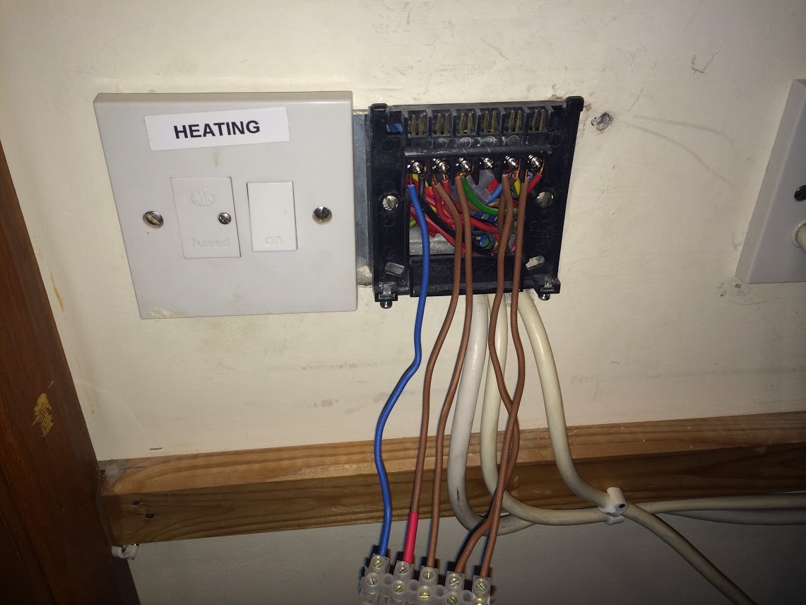
“The horrors that lurk behind the heating controller”
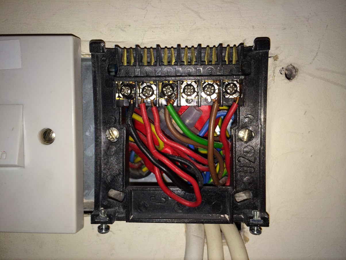
The first thing I did was to turn off the power to the heating system. I’m paranoid, so I turned it off at the fused connection to the left of the controller and also at the fuse box. I also wore rubber boots, and jumped in the air every time I touched a wire. Better safe than sorry, eh? And, rightly so it turns out. The fused connection unit did actually cut all the power to the heating system, but look carefully at the third connection from the left and you’ll see an earth wire being used to carry live current. This is against all the regulations. Whoever installed this system originally was clearly a free spirit. I was also quite impressed that they’d managed to squeeze all the connections in to a double gang back box. What a mess. Remember kids, only a competent person is allowed to fiddle with these things – they do a better quality job you see.
Looking at the zoomed in image you can see 6 terminals: N, L 1, 2, 3, 4.
N & L are self explanatory. 2 is not connected to anything, and so I don’t need to worry about it. So that leaves three connections that do something (1, 3 and 4). Exactly what I was expecting. One will be CH ON, one HW ON, and one HW off. Which is which?
Looking at the back of the controller unit it’s self:
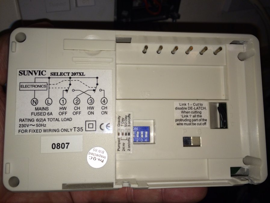
My theory is sound! 1 is HW OFF, 3 is HW ON, 4 is CH ON.
It looks like everything is connected as I had expected, but better safe than sorry. Let’s do a bit more testing:
I wired in a few bits of cable and then (not shown) removed the connections to the rest of the system (labelling where they came from when I removed them!). I left the L & N connected. To recap, I removed the existing wires from 1, 3 and 4 and replaced them with my cables which came down to some screw down connector blocks. The reason I put connector blocks on the end was two fold. Firstly, to make it easier to probe with my multimeter and secondly to stop me accidentally brushing against one of the cables and giving myself a shock. I also labelled the permanent live with a bit of red heat-shrink, just so I don’t get confused.
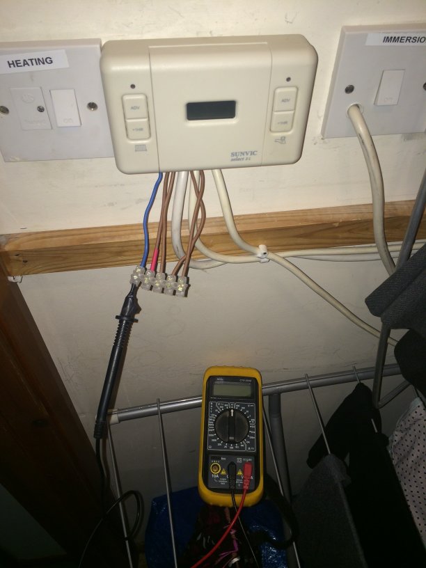
Putting the controlled back on, I hooked up my multimeter and switched through the options to see what happens when. My findings are below:
| 1 | 3 | 4 | |
|---|---|---|---|
| ALL OFF | 0 | 0 | 0 |
| HW ONLY | 0 | 240V | 0 |
| CH ONLY | 240V | 0 | 240V |
| BOTH ON | 0 | 240V | 240V |
Exactly what I expected. Point 1 must, therefore be “HW OFF”, point 2 “HW ON” and point 3 “CH ON” – which they are, as we saw from the back of the controller. I’m now confident enough with the set up to proceed with roughing out a block diagram for the controller and ordering the parts.
The plan
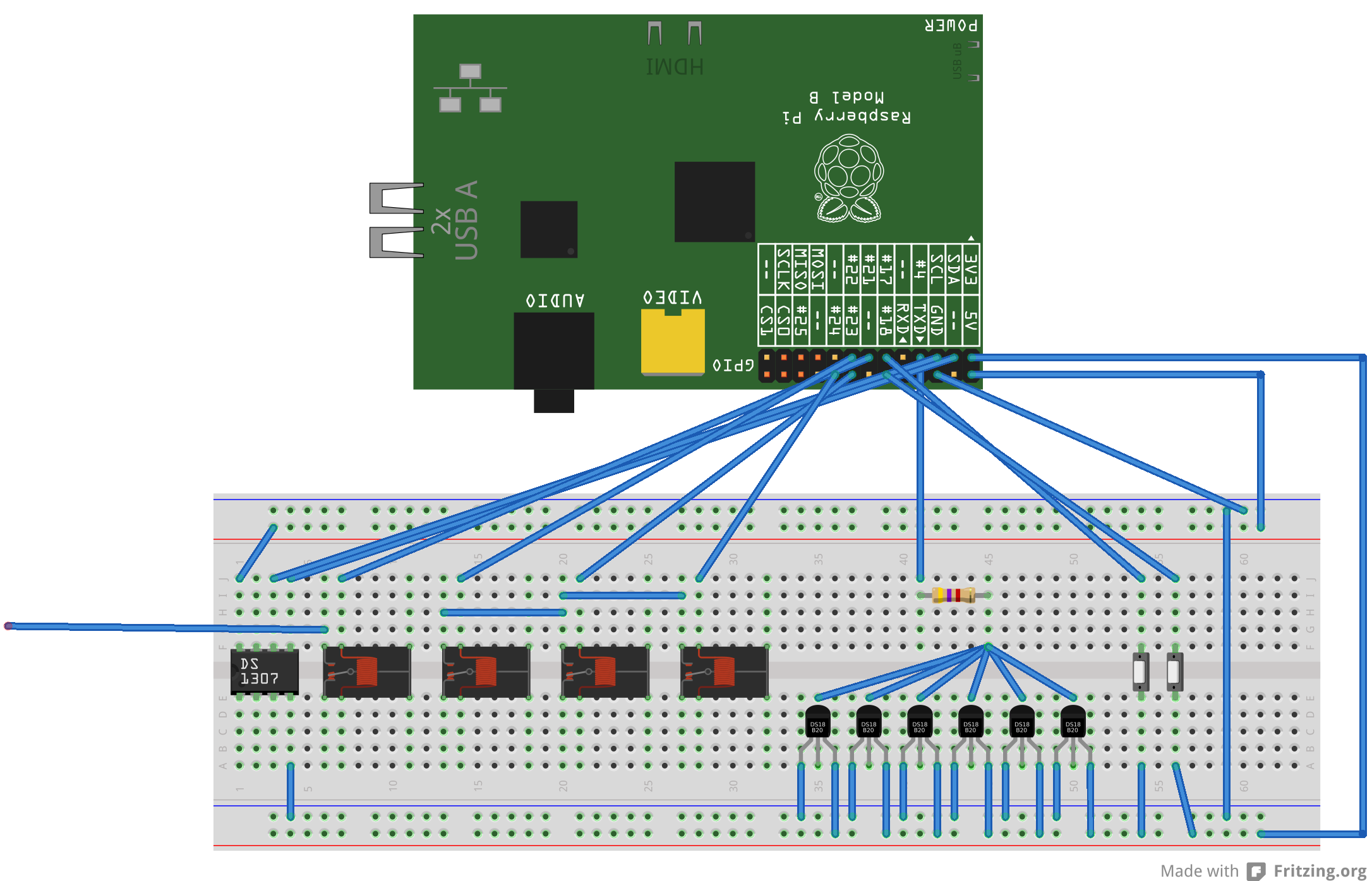
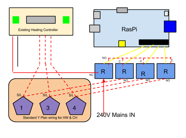
This rather unclear breadboard layout (with the awesome http://fritzing.org/home/) logically lays out what I intend to do. I’ve also added a crude block diagram for good measure.
First, I will add a real-time clock module. They’re cheap and easy to fit. This will provide the Pi with a source of time when it can’t talk to NTP servers, and so it will be able to turn things on and off at the right times, even when the network connection is down.
Next I will add four relays. I will take the main 240V incoming supply out of the existing controller and put it through relay 1. This relay will pass the supply on to the existing controller via the “Normally Closed” relay output. When I switch this relay, the supply to the existing controller will be dropped, and instead routed to the other three relays which will then be able to switch this current. These three relays will be wired in parallel with the existing controller connections, much like in the image above showing the test harness connected in to the controller connections. That is to say: one relay will go to point 1, one to point 3 and one to point 4. The existing safety features (thermostats in series in the circuits) are un-changed and so still offer the same protection. In order to activate heating or hot water we switch the relays as per the table above. By adding my new system in parallel and being able to easily switch between the two I can bring the RasPi powered one online gradually. A few hours here, a few hours there. And once I’m happy that it’s not going to go crazy I can leave it unsupervised for longer and longer periods. It also means that if I update the software and break something, we can still wash.
I will also add a number of 1wire temperature sensors. I will have three on the hot water cylinder: 1 at each of the top, middle and bottom. This will give me insight in to how much hot water is in the cylinder, and the temperature thereof. This is not intended to be a safety system. The temperature readings from these sensors will not be relied upon to switch things off in an emergency, that will be left to the original thermostats, but – we could use these readings as well to help make decisions. I will also fit a temperature sensors in the cold water tank, the primary header tank and somewhere outside. This will give me insight in to a couple of things: Firstly, how cold is the water in the CW tank, and what is the temperature outside? This has a direct effect on the number of showers that can be had from a given amount of hot water at a known temperature. Useful for trending too. Secondly, fitting a sensor in the primary header tank can report when the header tank is getting hot. Really, the header shouldn’t heat up too much. If it does then either the system is “pumping over” – where the pump is forcing water up the vent pipe pipe OR the water is so hot it has expanded enough to push water out of the vent, or I expect some combination of the two. Either situation is sub-optimal, and with a sensor in the header tank I get some visibility of what’s going on. I might also add a sensor to the boiler input and output, so get an idea of how much work the boiler is doing. Adding a sensor to each room would be a nice addition at some point too.
A couple of switches will be added for manually switching the hot water or heating on/off from the airing cupboard, where the current controller is situated and where the more senior visitors to Whizzy Towers will expect the heating buttons to be.
Shopping list:
- 1 x Real Time Clock. http://www.ebay.co.uk/itm/200929798800?ssPageName=STRK:MEWNX:IT&_trksid=p3984.m1439.l2649
- 4 mains rated relays. http://www.ebay.co.uk/itm/190950013824?var=490205033810&ssPageName=STRK:MEWNX:IT&_trksid=p3984.m1439.l2649
- Some 1wire temperature sensors. http://www.ebay.co.uk/itm/DS18S20-Temperature-Sensor-1-Wire-Dallas-Maxim-/130621920626
- A few meters of 0.75mm 5 core heat resistant flex (type 3095Y). http://www.ebay.co.uk/itm/5-Core-Heat-Resistant-Flex-Electrical-Cable-3095Y-0-75mm-/310663083027?pt=UK_BOI_Electrical_Components_Supplies_ET&var=&hash=item4854f67413
- A short bit of twin brown and earth for the connections between the 1st relay and the original controller live input.
- A 4k7 resistor
Couple that with a few odd bits of wire, some LEDs a bit of Python and we should have ourselves a Raspberry Pi powered heating and hot water controller which is relatively safe, easy to remove and cheap to build. Let’s see what happens when all the bits turn up. Should be here in a week or so.
Stay tuned.